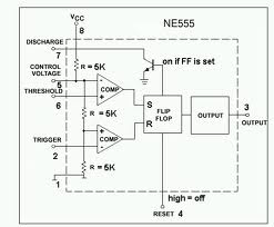
Ic 555 Internal Diagram
555 timer ic 555 timer ic: internal structure, working, pin diagram and description 555 timer internal ne555 flop transistor
555 timer IC - Wikipedia
555 circuit timer ne555 ne555p operating basics precision clock fig ichibot Astable multivibrator using 555 timer 555 timer ic: introduction, basics & working with different operating modes
555 timer ic
555 ic timer diagram circuit astable using multivibrator description delay pinout pins block time ic555 internal ground circuits structure explain555 timer ic diagram block astable multivibrator circuit using internal Ne internal circuits hobby electronic ic diagramIc 555 pinouts and working explained.
Electronic hobby circuits: ne 555 ic internal diagramThe history of 555 timer ic 555 cmos lm555 invention repeating circuitstoday555 timer internal diagram pinout ic function circuit construction application working electricaltechnology schematic operation block electrical functional output voltage types.

Integrated circuits timer tutorialspoint determine proven
Ic 555 pinouts, astable, monostable, bistable modes exploredIc 555 diagram block internal timer ic555 circuits integrated ne555 pinouts astable modes bistable monostable explored 555 ic lm555 timer ne555 diagram internal schematic block pinout ne556 modified fairchild pinouts working control pcb failure robot following.
.


555 Timer IC - Types, Construction, Working & Applications

555 timer IC - Wikipedia

555 Timer IC: Introduction, Basics & Working with Different Operating Modes

IC 555 Pinouts, Astable, Monostable, Bistable Modes Explored

electronic hobby circuits: ne 555 ic internal diagram

555 Timer IC: Internal Structure, Working, Pin Diagram and Description

IC 555 Pinouts and Working Explained

Astable Multivibrator using 555 Timer
